ELECTRIC Control

FIRE MONITOR

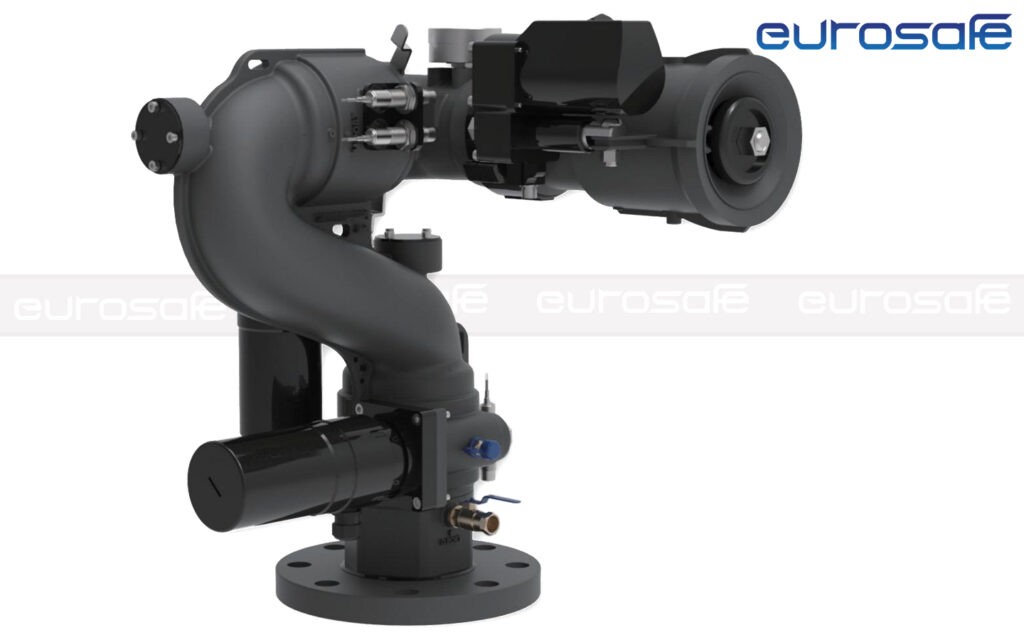
Model: ES0304

Eurosafe ELECTRIC CONTROL FIRE MONITOR ES0304 INDIVIDUAL POST PAGE
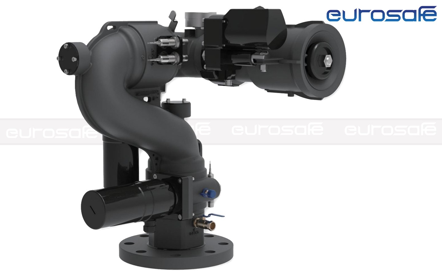
Eurosafe Electric Control Fire Monitor ES0304
MODEL NUMBERES0304/RCM-30W-CES0304/RCM-40W-C
RATING WORKING PRESSURE8 bar
WORKING PRESSURE RANGE6 bar ~ 16 bar
RATING FLOW RATE1800 LPM @ 8 bar1200-1800-2400 LPM @ 8 bar
WATER JETTING RANGEWATER 60M, FOAM 55MWATER 65M, FOAM 60M
MAX. FOG ANGLE120°
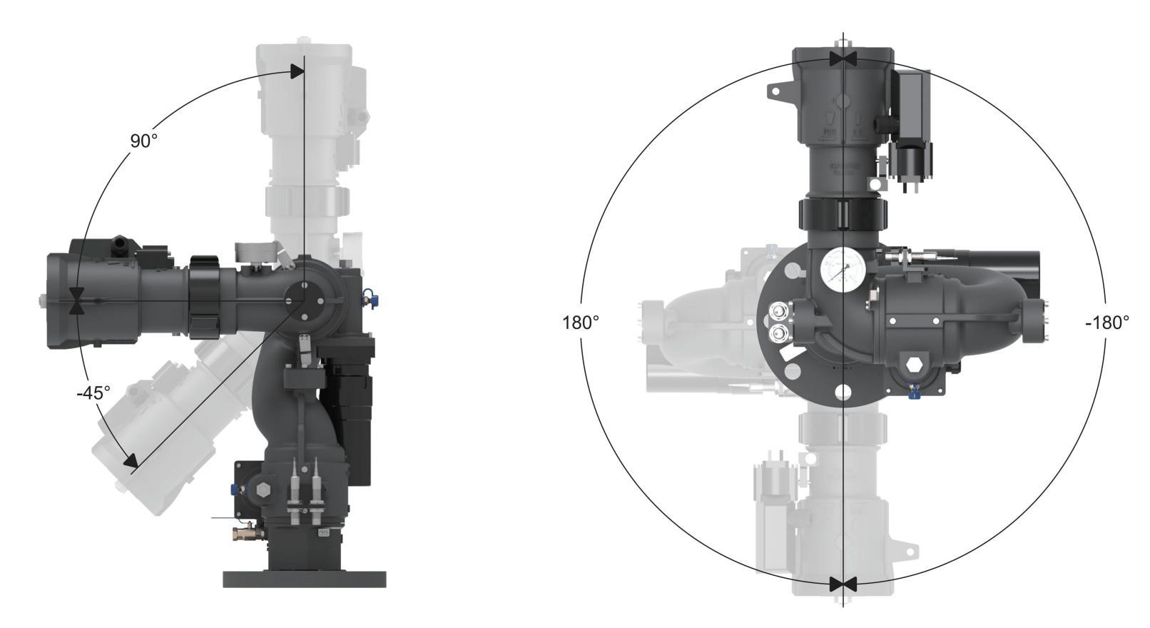
HORIZONTAL ROTATION ANGLE360° (customized)
VERTICAL ROTATION ANGLE-45° up to 90° (customized)
FIRE MONITOR POWER SUPPLYDC 24V
MATERIALFire Monitor - Aluminium alloy
WEIGHTApprox . 23 KGS
OUTLETMale 1.5”, 2.5” NH
INLET2”, 2.5” or 3 “ Flange
CONTROL1. Wired Joystick
2. Remote Control Transmitter
3. Manuall

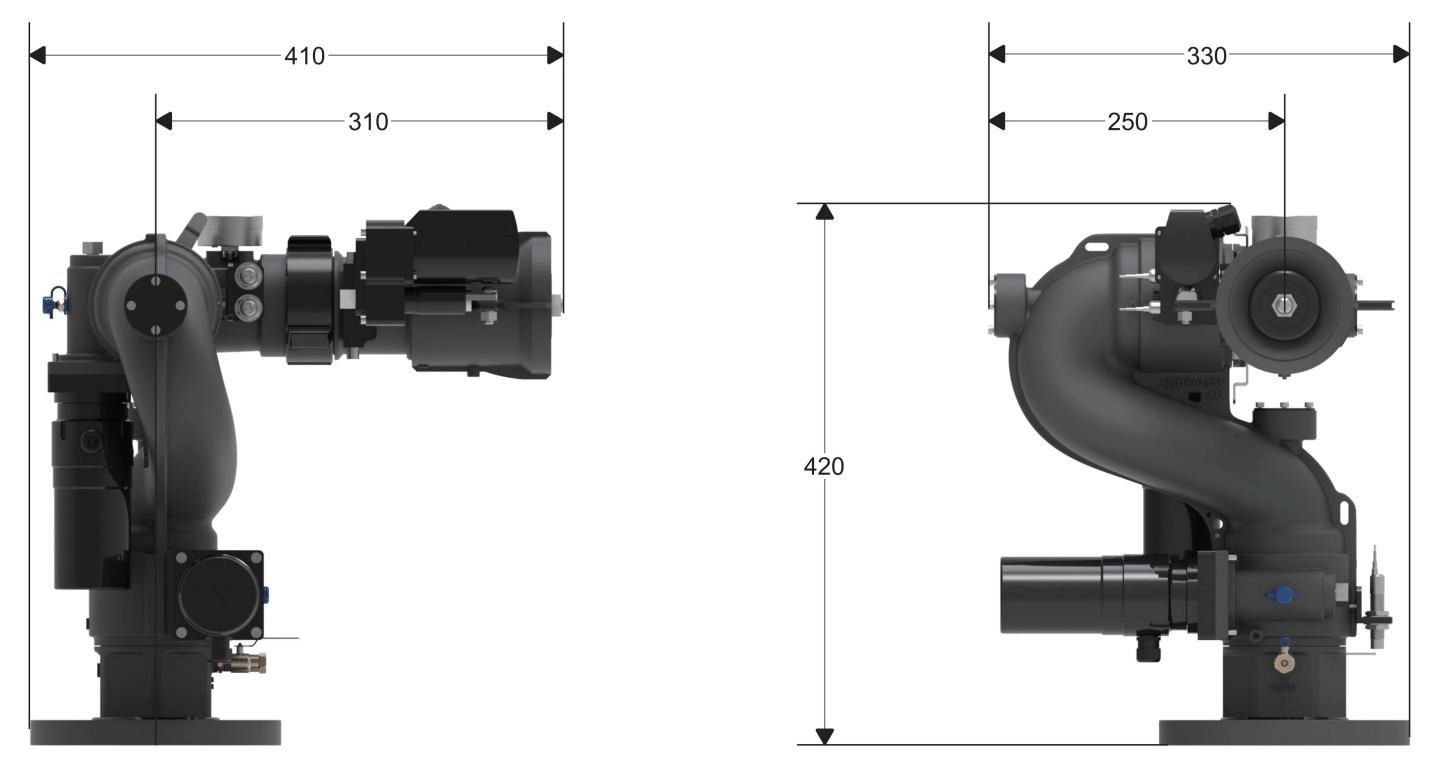
DIMENSION

ES0304 2

MAX WORKING ANGLE

ES0304 3

COMPONENT LIST

Eurosafe ES0304 Standard Components
NameFire Monitor (Standard)
Image Fire Monitor ES0304 Fire Monitor Image
ModelES0304
DESCRIPTION2.5 inch waterway
DC 24V Electrical motor
SS304 Worm, Aluminium Gear
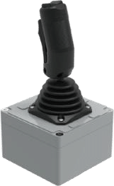
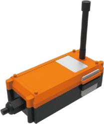
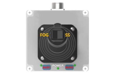
NameJoystick (Standard)RC Transmitter (Standard)
Image Joystick CTRL-J01 Joystick Image RC Transmitter CTRL-RCT01 RC Transmitter Image
MODEL NO.CTRL-J01CTRL - RCT01
DescriptionPower indicationMax. 150 meters RC Distance
Aluminium Alloy ShellIP65 Standard Sealed
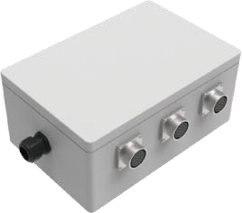
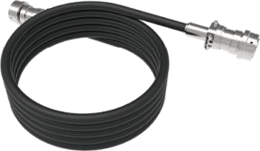
NameControl Unit (Standard)Cable (Standard)
Image Control Unit CU-01 Control Unit Image Cable CTRL-CB01/CB02 Cable Image
MODEL NO.CU-01CTRL-CB01/CB02
DescriptionCentrally connect the components
of The System
CB01 Length 5m
Aluminium Alloy CoverCB02 Length12m
Other length available

OPERATION INTRODUCTION

The Fire Monitor is able to be controlled by Control box and RC transmitter:

Joystick Operation Guide

ES0304 6 Joystick Operation Guide
Eurosafe Fire Monitor Button Descriptions
BUTTONSDESCRIPTION
POWERGreen Indicator Light, Always on to indicate the power on-state.
AUX1Reserved auxiliary button,customized function.
AUX2Reserved auxiliary button,customized function.
FOG/SSFog spray / Straight stream
HANDLETurn up-down-left-right of the fire monitor.

PS: The function of opening and closing the water supply valve can be selected according to customer needs

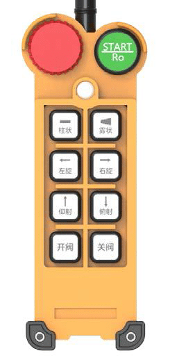
RC transmitter Operation Guide:

ES0304 5 RC transmitter
RC Transmitter Operation Guide

EMERGENCY STOPThe red button, press to disconnect the signal connection with Fire Monitor
STARTThe green button, connect the signal connection with Fire Monitor
JETStraight stream
FOGFog spray
LEFTTurn left the nozzle horizontally
RIGHTTurn right the nozzle horizontally
UPTurn up the nozzle vertically
DOWNTurn down the nozzle vertically
OPENOpen the electrical valve (Not standard)
CLOSEClose the electrical valve (Not standard)

PS: The function of opening and closing the water supply valve can be selected according to customer needs

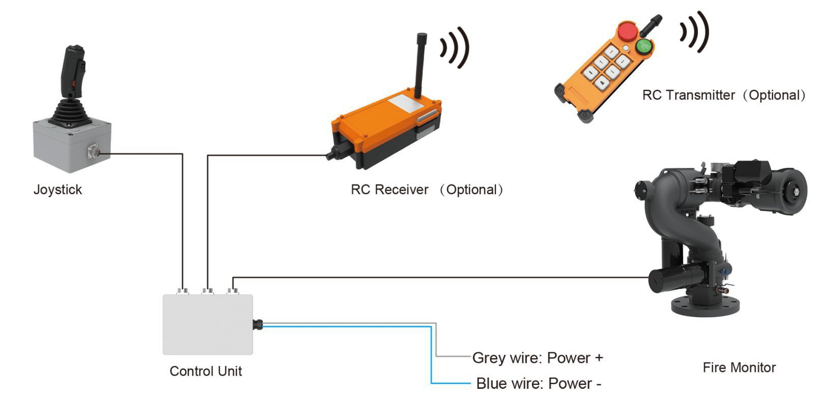
WIRING

ES0304 4 Wiring